

THE AUTONOMOUS UNDERWATER VEHICLES LAB
The AUV Lab at MIT Sea Grant was created in 1989 to develop an underwater vehicle that was both highly capable and cost-effective. Several families of vehicles were developed, including the Odyssey class, which became the foundation of research spin-off Bluefin Robotics.
Since then, the AUV Lab has developed many other autonomous underwater and surface vehicles, from the Remote Explorer 4 (REx 4), a 5 meter, fully unmanned autonomous surface vessel, to the Sea Beaver, an open-source, 1 meter AUV. The AUV Lab builds partnerships with other institutions and commercial entities, including a multi-year collaboration with Mercury Marine developing a fully autonomous 8-meter Boston Whaler, “RoboWhaler“, and ongoing AUV development with the Naval Undersea Warfare Center. Current development efforts include advances in marine perception, data fusion, collision avoidance, and path planning.
Through MIT Sea Grant, the AUV Lab is actively engaged in the MIT community and has many ongoing projects with students from the undergraduate to post-doc level. The lab also has facilities in the Marine Autonomy Bay at the MIT Sailing Pavilion on the Charles River in Cambridge, MA. Boston Harbor and Massachusetts Bay are also accessible, providing both inner harbor and open ocean environments to test vehicles and algorithms.
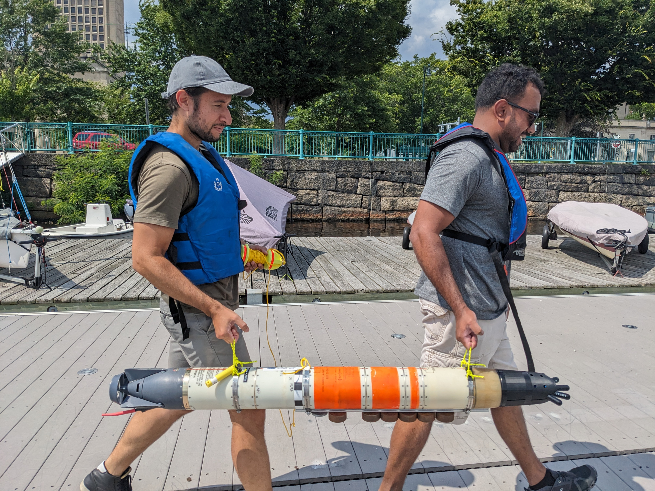
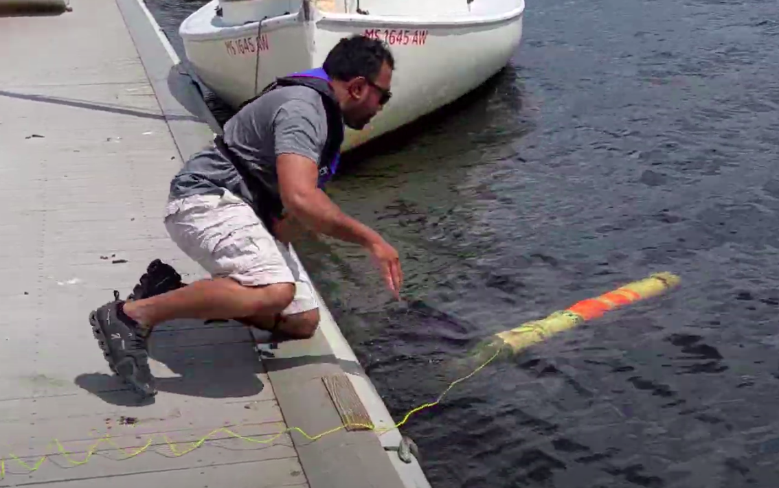
MIT Sea Grant researchers prepare to launch Sea Badger, an advanced variant of the Navy MK-39 EMATT vehicle.
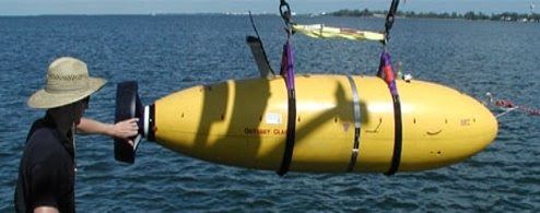
Odyssey-class vessel developed at the AUV Lab
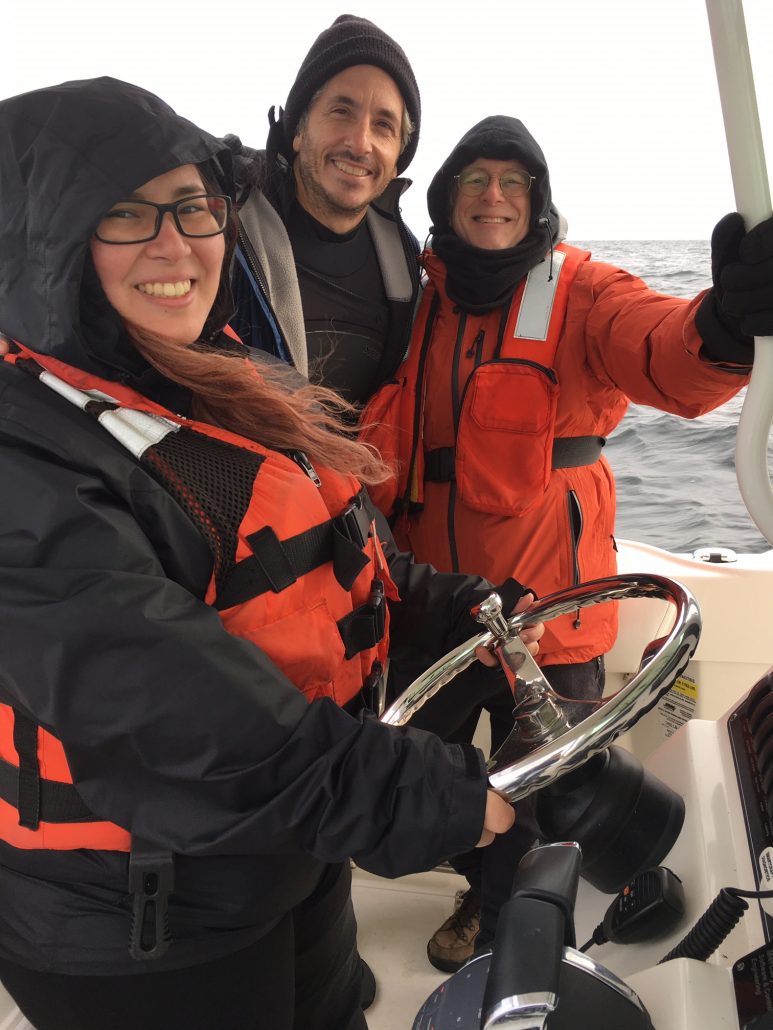
An MIT undergraduate student takes the wheel with MIT Sea Grant Visiting Artist Keith Ellenbogen and AUV Lab Research Engineer Michael Sacarny.
MARINE PERCEPTION
Robust and low-cost perception technologies for the marine environment:
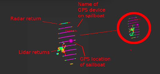
- Multimodal Sensor Fusion: Creating actionable data through fusing sensors such as camera, infrared, radar, and lidar
- Machine Vision: Developing machine learning models to detect and classify objects of interest in the marine environment
- Marine Datasets: Creating coordinated marine datasets for understanding marine autonomy and perception
AUV DEVELOPMENT
True to its name, the AUV Lab has multiple AUVs deployed or under development:
- The Sea Beaver is a low-cost, open-source small AUV intended for education. It is being developed with support from Saab, Inc.
- The Sea Badger is the latest in a line of advanced variants of the Navy MK-39 EMATT anti-submarine training vehicle. Sea Badger has swarm and submerged convoy capabilities. Prior versions demonstrated high agility from a novel, morphing fin mechanism.
- Supporting these advancements is MIT-developed HydroMAN software, a self-learning, independent underwater navigation engine.
Maiden voyage of the Sea Badger
AUTONOMOUS SAILING
The AUV Lab is adding advanced sailing behaviors, survey, and swarm capabilities to a 2 m sailboat developed by Marine Robotics, LLC. The vessel has already demonstrated autonomous population monitoring of acoustically-tagged winter flounder in Boston Harbor. The sailboat is intended to promote oyster recovery and environmental monitoring in Chesapeake Bay. Current research is focused on improving fundamental sailing behavior, adaptive survey patterns, and testing simulation.
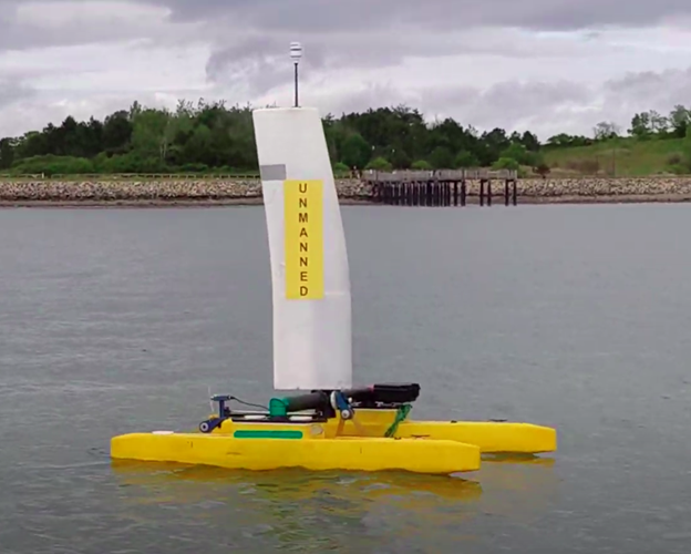
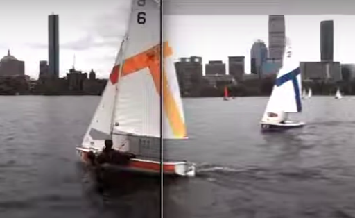
Autonomous sailboat tracking winter flounder in Boston Harbor in June, 2023
